
Why start with the UNO R3?
The Arduino UNO R3 is based on the ATmega328P and has 14 digital pins and six analog inputs. Six digital pins support PWM. It is a useful board for learning LEDs, buttons, analog sensors and basic actuator control. QuadBlock lets you assemble supported operations as blocks and inspect the Arduino sketch they generate. The UNO R3 has no built-in Wi-Fi; connected examples require appropriate additional hardware or a different board.
Set up the desktop workflow
- Connect the UNO R3 using a data-capable USB cable.
- Choose Arduino UNO R3 in the board selector.
- Select its serial port. If no port appears, check the cable, driver and operating-system device list.
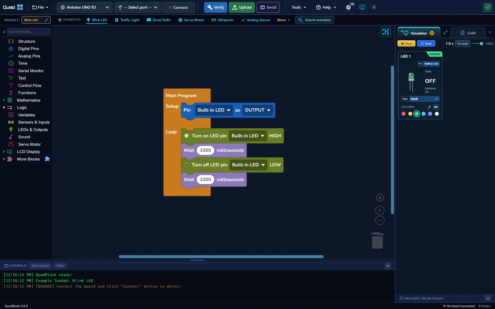
- Start with the Blink LED example and inspect the generated Code.
- Verify, then Upload. Close other serial applications if the port is busy.
A successful simulation and a successful compilation are different checks. The simulator evaluates supported virtual behavior; the compiler checks whether the generated sketch can be built with the selected board package.
Know the pins you are using
Digital pins can read or drive a logical state. On UNO R3, PWM is available on pins 3, 5, 6, 9, 10 and 11. PWM changes duty cycle; it is not a continuously variable analog output. A0–A5 read analog voltage. The usual 10-bit analog reading spans 0–1023. UNO R3 uses 5 V logic; always check the ratings of any attached module.
The built-in LED is associated with pin 13. It is the simplest first output because no external LED wiring is needed. Pins 0 and 1 are used by the hardware serial interface, so avoid assigning them to unrelated hardware while relying on USB serial communication.
Three practical projects to build
- Blink the built-in LED with a one-second delay
- Print a potentiometer reading to the Serial Monitor
- Move a positional servo between safe test angles
For an LED threshold project, read A0, compare it with a numeric threshold and place the LED commands in an IF/ELSE block. Test values around the threshold in the simulator before wiring a real sensor.
Check the virtual result, then the real circuit
Use the Simulator tab to see supported component cards. Their values follow the program and virtual input controls. A real sensor can be noisier than a slider, and a real motor can draw more current than the board can supply. Keep the simulator as a logic check and validate wiring and power separately.
If Blink works in the simulator but not on the UNO R3, check the selected board and port, upload result and whether the intended LED pin is used. The physical board and simulator are independent executions and do not share a synchronized clock.
Board reference: Arduino UNO Rev3 documentation.
Questions before you start
Does UNO R3 support the UNO R4 WiFi matrix blocks?
No. The UNO R3 has no built-in LED matrix or Wi-Fi. Use compatible external hardware and blocks, or select a board with the required feature.
Can I upload a block program to the UNO R3?
Yes. Select UNO R3 and its port, build the supported program, then Verify and Upload using the desktop app.