
Wire a simple analog input
For this UNO R3 example, connect the two outer terminals of a typical 10 kΩ potentiometer to 5 V and GND. Connect the center wiper to A0. Check the part’s terminals before powering the circuit. Turn off power while changing wiring. A0 should receive a voltage within the board’s allowed input range.
Build a reading loop
- Select UNO R3 and start Serial at 9600 baud in Setup.
- In Loop, read analog pin A0 into a variable such as reading.
- Print a label such as Sensor A0: and then print the reading.
- Wait 200 milliseconds before the next reading.
The usual UNO R3 reading is 10-bit: 0–1023. Near one end of the knob travel the result approaches zero; near the other it approaches the maximum. The exact endpoints depend on wiring and the real component. Reversing the outer connections reverses the direction of change.
Test the virtual input
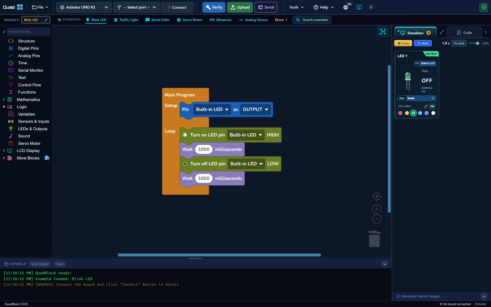
In the Simulator, find the supported analog-input card and adjust Sensor input or its numeric value. Watch the simulator serial output. This tests the program’s response to a chosen reading, not the physical potentiometer’s wiring. The illustration on this page is a general workspace example; use your A0 project to see its own card.
Add a threshold
Compare reading with 512 inside an IF/ELSE block. Turn an LED on in one branch and off in the other. Test readings of 511, 512 and 513 so the boundary is unambiguous. A greater-than comparison differs from greater-than-or-equal at exactly 512. This is where a virtual input is particularly useful.
Upload and troubleshoot
Verify and Upload to the UNO R3, then open its Serial Monitor at 9600 baud. Rotate the knob and confirm the reading changes. A constant value can indicate a wiring mistake; a floating input can produce unstable readings. Make sure the wiper actually reaches A0 and the grounds are connected.
ESP32 analog ranges and supported pins differ. Do not copy the UNO R3’s 5 V wiring to ESP32 GPIO. Read the ESP32 guide before moving this project to another board. Arduino reference: analogRead.