
What you need
Use an Arduino UNO R3, a data-capable USB cable and the QuadBlock desktop app with the appropriate board toolchain. This tutorial uses the built-in LED, so no external LED wiring is needed. You can first test the supported behavior in the Simulator without connecting the board.
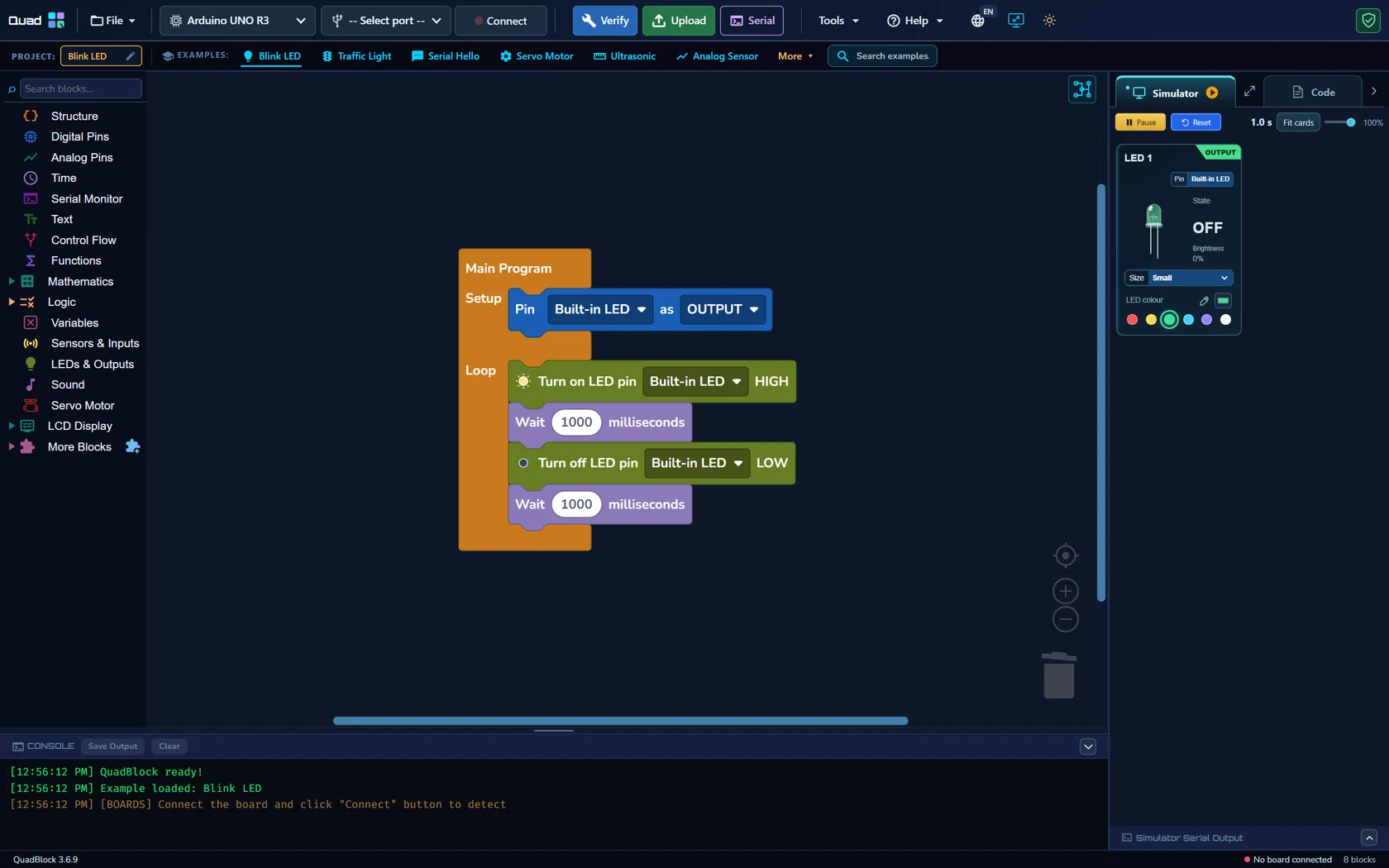
Build the Setup and Loop
- Select Arduino UNO R3. Open the Blink LED example or start with a Main Program block.
- In Setup, configure Built-in LED as OUTPUT. On UNO R3 it corresponds to pin 13.
- In Loop, turn the LED HIGH and add Wait 1000 milliseconds.
- Turn the LED LOW and add another Wait 1000 milliseconds.
The loop repeats after the final wait. Each complete cycle takes approximately two seconds, ignoring small execution overhead. Removing the waits would change the output too quickly to observe as an ordinary blink.
Inspect the generated sketch
Open Code. You should see pinMode for the LED output, then digitalWrite HIGH, delay, digitalWrite LOW and delay in the loop. The block value of 1000 milliseconds becomes a one-second delay. This is a useful first connection between visual programming and Arduino C++.
void setup() {
  pinMode(LED_BUILTIN, OUTPUT);
}
void loop() {
  digitalWrite(LED_BUILTIN, HIGH);
  delay(1000);
  digitalWrite(LED_BUILTIN, LOW);
  delay(1000);
}
Simulate, verify and upload
Open Simulator and confirm the LED alternates between ON and OFF. Then connect the UNO R3, select its port, Verify and Upload. Read the upload result in the main console. The physical LED should blink after a successful upload. Its phase will not necessarily match the independently running simulator.
Try one deliberate change
Change both waits to 500 milliseconds. The LED now completes a cycle in approximately one second. Change only the ON wait to 200 milliseconds and leave the OFF wait at 1000 to create a short flash. Check the simulated behavior, then upload again to update the physical board.
If the LED stays off, check the board, pin, output configuration and upload result. A power LED on the board is not the programmable built-in LED. Continue with reading a potentiometer when Blink behaves as expected.
Questions before you start
Why does the simulator blink at a different moment from my board?
They start and execute independently. Matching blink intervals do not imply synchronized ON and OFF phases.