Microbit
Microbit Lesson-18: 1602 i2c LCD Display
Introduction
Over here we will show you what is the I2C LCD 1602 Display and how it works, you can follow the next lesson to get how to use the I2C LCD 1602 Display with the micro bit.
Parts Needed
- 1x micro:bit
- 1x Micro B USB Cable
- 1x micro:bit Breakout (with Headers)
- 1x Breadboard
- 5x Jumper Wires
- 1x I2C LCD 1602 Display
About i2c LCD 1602 Display
The integration of an LCD display greatly facilitates the interactivity of the project you are developing, allowing the user to directly read some output parameters. These values can be either a simple text or numerical values read by the sensors, such as temperature or pressure, or even the number of cycles that the Arduino is performing.
However, these displays have a small problem. When they are connected to a microcontroller (such as Micro bit for example), these displays require virtually many connection PINs occupying practically almost all available IO and leaving the multiprocessor few outputs for any other devices and sensors. This problem has been solved thanks to the communication on the I2C bus.
The LCD1602 display has an integrated microchip that manages this type of communication, and then all of the input and output information are limited to only two PINs (excluding power supply). I2C is a type of serial bus developed by Philips, which uses two bidirectional lines, called SDA (Serial Data Line) and SCL (Serial Clock Line). Both must be connected via pulled-up resistors. The usage voltages are standard as 5V and 3.3V.
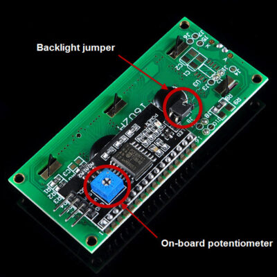
The blue potentiometer on the I2C LCD1602 (see the figure below) is used to adjust the backlight for better display. And there is a jumper on the board, if you take away this jumper , the backlight will always be off.

Extension: Makecode I2C LCD1602 package for micro:bit
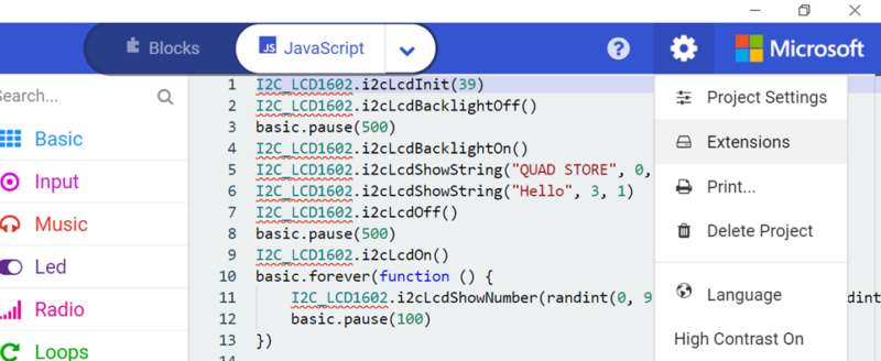
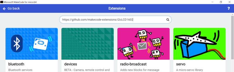
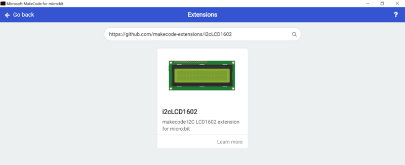
First you need to install the extension required for I2c LCD1602. In order to do it Open your microbit makecode project Click Setting Icon -> Extensions -> in search bar add below Package link and click search
https://github.com/makecode-extensions/i2cLCD1602
IMPORTANT: I2C Address
| PCF8574 | PCF8574A |
|---|---|
| 0x27 | 0x3F |
- PCF8574: 39
- PCF8574A: 63
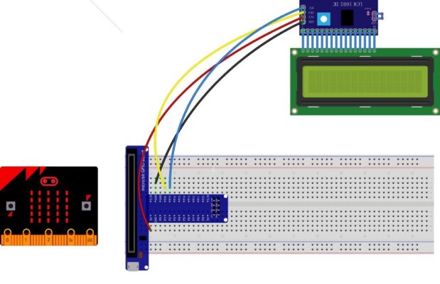
Wiring Diagram for the Experiment
Connection for 1602 LCD setup:
| Microbit Breakout | LCD1602 |
|---|---|
| 5V | VCC |
| GND | GND |
| P19/SCL | SCL |
| P20/SDA | SDA |
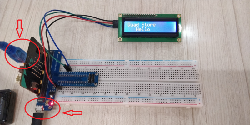
Note: Because the output power of the micro bit is limited, please connect the USB cable to the USB port on the micro bit when downloading the program. After the program is successfully downloaded to the board, connect the USB cable to the USB port on the expansion board, ensure the LCD display can work perfectly.
Run Your Script

Either copy and paste, or re-create the following code into your own MakeCode editor by clicking the “Edit” Option in the upper right-hand corner of the editor window. You can also just download this example by clicking the download button in the lower right-hand corner of the code window.
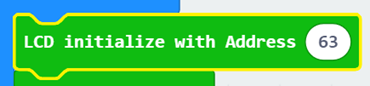
Overhere, the device I2C address is “0x3F”, please enter “63” to the address bar.
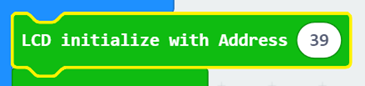
If your the I2C address of this device is “0x27”, so we type “39” in the address bar.
RESULT
After downloaded this code to your micro bit, pull out the USB line and insert the USB line to the expansion board, you will see “Quad Store”,”Hello” on the LCD screen.
Note:
If the screen is not bright, please check the wires. If the screen is bright, but you do not see the above results, please check you I2C address. Also adjust the potentiometer at the back side if you want to see the letters bright.
.